Vehicle manufacturing is a complex process where every stage — from design to final inspection — must align for optimal performance and safety.
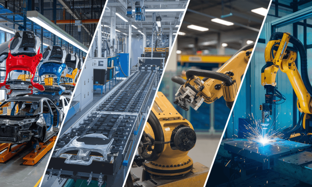
Modern automotive manufacturing typically follows five key stages: stamping, welding, painting, assembly and inspection. Among these, BIW (Body-in-White) welding plays a critical role in shaping the vehicle’s structural integrity.
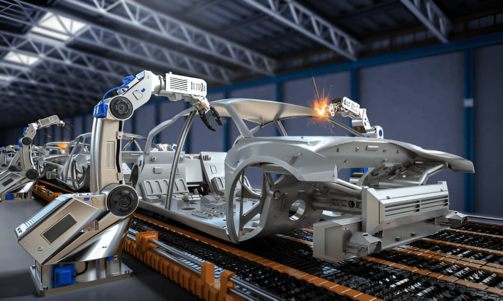
This is the stage where all sheet metal components — including the roof, floor, pillars and side panels — are welded together to form the vehicle’s skeletal frame, before painting or adding parts like the engine, trim or electronics.
Why does it matter so much? Because a weak weld or small misalignment here can impact everything — from crash safety and ride quality to how the doors close.
Despite its importance, BIW welding remains one of the most error-prone stages in car manufacturing. Problems like misalignment, weld splash, weak joints, and missed inspection points are surprisingly common.
And the cause? It’s not always automation. More often, the issues arise from poor fixture design, inconsistent part quality or missing real-time feedback.
In this blog, we’ll explore these common challenges and share practical solutions to improve BIW welding precision and reliability.
Want to bring more precision and control to your BIW welding process? Explore our Industrial Automation Services to improve accuracy and reduce failure risks across your manufacturing line.
What is BIW (Body-in-White)?
Body-in-White, or BIW, is a critical stage in automotive manufacturing where the vehicle’s sheet metal components are welded together to form its structural shell. At this point, the body has no paint, no trim, and no mechanical or electrical systems — it’s the raw framework that gives the vehicle its shape, strength and dimensional foundation.
Before reaching this stage, panels are shaped through stamping, blanking and rolling. Once formed, they're transferred to the BIW line for welding and assembly.
The BIW structure includes key elements: the floor pan, side panels, roof, pillars and rear body. These components are welded with tight tolerances to form a rigid, self-supporting shell. This shell determines the vehicle’s crash performance, torsional stiffness and dimensional accuracy — all critical to vehicle performance and manufacturing efficiency.
What’s Included in the BIW Stage?
The BIW line includes multiple joining and preparation steps, like:
- Welding of structural components
- Hemming of closures such as doors, hoods, and roof panels
- Sealing and applying anti-corrosion treatments to joints
- Designing the right jigs and fixtures to ensure accurate positioning throughout the process
At this stage, the body’s geometry is finalized, including mounting points for future systems like the engine, suspension and interior modules.
Once the BIW is complete and structurally sound, it moves to the paint shop for surface treatment and coating before heading to final assembly.
Welding in BIW
Welding is the backbone of BIW. Hundreds of joints must be created with high accuracy to ensure structural strength and consistency across every unit. These welds directly affect:
- Dimensional accuracy (so parts align perfectly in later stages)
- Torsional rigidity (crucial for ride, handling and NVH performance)
- Crashworthiness (how well the car absorbs impact energy)
Even a slight misalignment or weak weld can affect the whole vehicle manufacturing line, leading to assembly issues, more rework and long-term durability issues.
Common BIW Welding Methods
Different welding techniques are used across the BIW line depending on part thickness, joint type, and design intent:
- Resistance Spot Welding (RSW) – Most widely used for joining thin sheet metal panels.
- MIG/MAG Welding – Used for thicker parts or joints that require stronger welds.
- Laser Welding – Offers high-speed, high-precision welds with minimal distortion.
- Laser Brazing – Ideal for visible joints (like roof seams) where appearance matters.
These processes are often fully automated — but precision still depends on quality parts, stable fixtures, and real-time process control.
The Top 7 Body-in-White (BIW) Welding Challenges
Even with advanced robots and automation in automotive industry, BIW welding continues to face problems that can slow down production and affect overall build quality.
Let’s look at some of the most frequent Body-in-White welding issues and how you can solve them with smarter, more practical solutions.
1. Inaccurate Fixture Design and Positioning
In BIW welding, precision starts well before the weld. It starts with how each part is held in place. Fixtures are responsible for accurately positioning body panels during welding. The locator holes and reference points built into these fixtures define the car’s geometry.
In other words, they control everything from panel alignment to structural stiffness and crash performance. Even a minor misalignment in fixture design can cause dimensional deviations, poor fit-up, or gaps — all of which compromise weld integrity and overall vehicle quality.
This is especially critical in robotic welding lines, where repeatability is key. Even the most advanced welding robot cannot correct for a poorly designed or worn-out fixture.
Solution:
- Use high-precision welding fixtures with strong workholding and reliable clamping systems to ensure proper part alignment.
- Design fixtures with tolerance control to accommodate minor part variations.
- Incorporate sensor-based feedback to confirm correct part placement before welding.
- Periodically audit and recalibrate fixtures to maintain positional accuracy.
2. Weld Splash in Resistance Spot Welding
Resistance Spot Welding (RSW), the most commonly used method in BIW welding, is ideal for joining overlapping sheet metal in structures like doors, floor panels and side frames. Its speed and simplicity make it essential in high-volume vehicle manufacturing.
A frequent issue in resistance spot welding is the expulsion of molten metal — commonly referred to as weld splash. This not only compromises the structural integrity of the weld but also affects downstream processes like painting and sealing.
Solution:
To reduce the chances of weld splash during resistance spot welding, here are a few steps you can take:
- Maintain consistent sheet surface conditions and thickness.
- Monitor and replace electrode caps to prevent uneven current flow.
- Use pre-heat or multi-pulse weld schedules to reduce thermal shock.
- Optimize weld force and current balance through process tuning.
3. Inconsistent Weld Quality and Inspection Gaps
Even with robotic automation, weld quality isn't always consistent across different areas of the car body. Some joints may look perfect, while others fall short on strength or precision. That’s a problem — especially in critical zones like battery enclosures or crossmembers, where every weld impact safety.
What causes this? Variations in material, heat distortion, joint gaps and small deviations in robot paths. These issues can lead to weak penetration, inconsistent bead profiles, or missed spots altogether.
Now add inspection into the mix. Most BIW lines still rely on manual checks or basic sensors, which just aren’t enough. At high production speeds, it’s easy to miss a flaw and that flaw can show up much later as a costly rework or structural failure.
Solution:
- Standardize inputs and tighten tolerance bands at the design stage.
- Use seam tracking systems (like 3D laser vision) to adjust robot paths on the fly.
- Monitor key weld parameters in real time (e.g. voltage, current, arc length) to catch issues early.
- Automate weld inspections with cameras, sensors, or 3D scanners.
- Combine inspection systems with real-time process monitoring to detect deviations as they happen, not after the fact.
4. Welding Challenges with Tailor-Welded Blanks (TWBs)
Tailor-Welded Blanks (TWBs) are widely used in modern car bodies to optimize weight and performance. These are sheet metal parts made by joining two or more pieces of steel with different thicknesses or grades — often using laser welding. You’ll typically find them in door inners, floor pans or side frames, where structural performance and material efficiency are critical.
But welding TWBs isn’t simple. Their large size and mixed material properties demand high precision. In laser welding, even a slight deviation in the robot path — say, more than 100 microns — can cause weld defects or structural weaknesses. Maintaining accuracy across large parts at high speeds is a constant battle.
Solution:
- Use seam-tracking laser vision systems that guide the weld path in real time.
- Go for zero-backlash actuators on welding robots to reduce motion errors.
- Adjust robot programs based on each part’s behavior to compensate for springback or distortion during welding.
- Implement pre-weld part verification to catch inconsistencies before welding begins.
5. Poor Weld Planning and Geo Spot Strategy
One of the biggest challenges in automotive welding — especially when using resistance spot welding (RSW) — is getting the weld sequence right. This is especially true for Geo Spot Welds (GSWs). These are the first critical welds applied to the structure. And they define the geometry of the assembly. If GSWs are misplaced or not planned correctly, the entire body can go out of alignment.
Re-spot welds are added later to enhance structural stiffness and strength, but they don’t define geometry. So if the GSWs are off, no amount of re-spotting can correct the misalignment. The result? Panel mismatches, NVH issues, and final assembly fit problems — all of which are preventable with better upfront weld planning.
This issue is compounded in some stations — especially stationary spot welding setups without robots. Here poor fixture design or limited access can make precise GSW application even more difficult.
Solution:
- Define and validate GSW points early in the design phase using virtual simulations.
- Involve fixture and robot teams in planning to ensure access, clampability, and stability.
- Use digital twins or offline programming tools to simulate and optimize weld sequences.
- Audit stationary welding stations for accessibility and consistency.
- Ensure re-spot planning supports rigidity without compensating for poor GSW execution.
6. Thermal Distortion and Panel Warping
Many BIW welding methods — like MIG, MAG, and laser welding — generate intense heat in small, focused areas. If this heat isn’t properly controlled, it can cause thermal distortion. Panels may warp, assemblies can shift out of alignment, and the body may end up outside of dimensional tolerances.
It’s particularly common in large surface areas like EV battery enclosures, where heat input is not evenly distributed. Once distortion sets in, it can throw off door alignment, increase NVH (noise, vibration, and harshness), or lead to problems in the final assembly — all of which mean expensive rework.
Solution:
- Use optimized weld sequences and staggered weld patterns to balance heat distribution.
- Design joints with proper gaps and backing support to reduce thermal buildup.
- Apply precision clamping and modular fixtures to hold parts steady during welding.
- Run robotic simulations ahead of production to predict and reduce distortion.
7. Robot Reach and Accessibility in Large BIW Assemblies
As car bodies become more complex and modular, welding robots are expected to handle larger parts like full side frames or roof panels with high precision. But here’s the problem: even large six-axis robots have reach and flexibility limits. In tight or deep cavities, it becomes difficult to maintain the required torch angle or follow the exact weld path — especially in laser or arc welding, where precision is non-negotiable.
This often results in missed welds, inconsistent seams or the need for additional repositioning systems — all of which slow down the cycle time and increase operational cost.
Solution:
- Use multi-robot setups or coordinated motion systems to access hard-to-reach areas without compromising speed.
- Use modular welding cells with programmable positioners or turntables to rotate parts into optimal welding positions.
- Integrate adaptive vision systems that can correct path deviations when physical access is constrained.
- Where robot access is limited, evaluate alternative joining methods like clinching or structural adhesives in non-critical zones.
Optimize your BiW Welding Line with Sedin Engineering.
BIW welding may be one of the most automated stages in automotive manufacturing. But real-world success still lies in precision, consistency and smart design decisions.
From weld splash and panel distortion to inspection challenges and alignment issues, many of these problems can be traced back to how well the process is planned and supported — long before the robot ever strikes an arc.
At Sedin Engineering, we support automotive manufacturers with:
- Precision fixture design for accurate part positioning and repeatable welds
- Laser vision systems that enable seam tracking and real-time weld quality control
- Robotic simulation to predict and eliminate issues before they happen
- And end-to-end automation integration for welding lines that work, reliably and efficiently
Looking to optimize your BIW welding process? Contact us. Our engineers will connect with you to explore how we can bring precision and control to your line, from design to automation.


