To meet the client’s requirements and address the challenges of complex structural designs, Sedin’s expert engineers utilized a comprehensive approach that enabled timely product completion and installation, presenting enhanced versions to the clients.
We categorized the solution into 4 phases.
Phase 1: Load Calculations
Before the design phase, we conducted detailed load calculations, including live, dead, wind, and seismic loads, in compliance with AISC standards. This ensured the structure would meet all strength and stability requirements:
- Material: Structural steel grade S275, with a yield strength of 275 MPa, was chosen for its durability under static and dynamic loads.
- Weight: The structure was estimated to weigh 250-260 tonnes, including beams, columns, bracing, and roofing.
- Wind Resistance: The design could withstand wind speeds of 45 m/s while adhering to local safety standards.
Phase 2: Design Calculations
In this phase, we selected the appropriate sizes for the columns, beams, and foundation elements, ensuring they can safely handle the applied loads:
- Beam and Column Design: Beam and column sizes were selected based on analysis of bending moments and buckling loads, to ensure they could safely support the applied loads.
- Foundation Design: The foundation was designed with isolated footings, considering a soil-bearing capacity of 150 kN/m². We checked the bearing pressure to ensure the actual soil pressure is within safe limits for stability.
Phase 3: Detailed Design
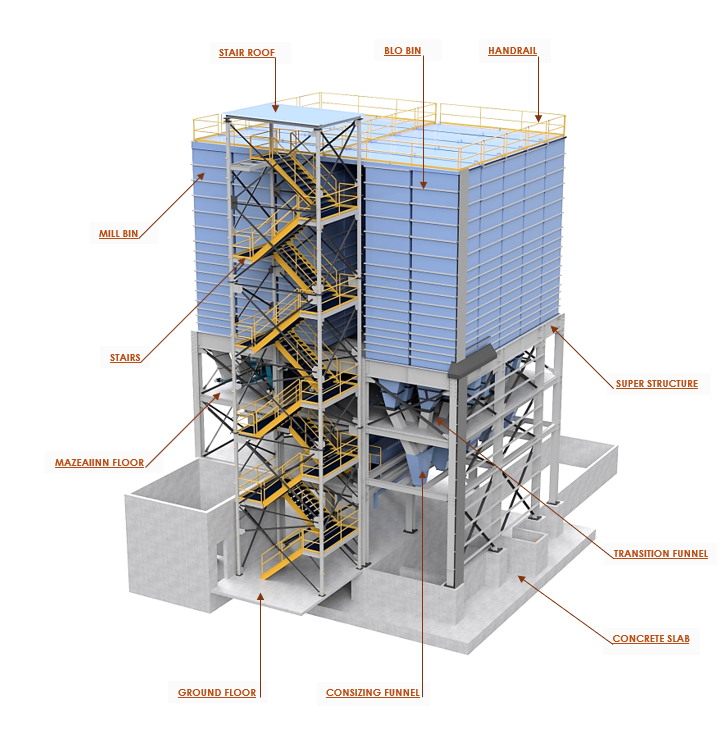
In this phase, our team designed a 3D CAD structure to support 20 grain storage bins, each holding 53,000 liters and weighing 5-8 tonnes. The structure was built to handle various loads and weather conditions.
The design also included essential components like bin assemblies, screw conveyor systems, hopper assemblies, combining funnels, and transition chutes. To ensure reliable performance, we focused on providing adequate support for each component and maintaining uniform load distribution across the structure.
Key Design Features:
- Steel Structure: Design included steel sections for poles, beams, bracing, handrails, stairs, and platforms.
- Beams and Columns: Symmetrical columns and beams were designed using square, rectangular or circular hollow sections and I-sections, as per the requirements. CHS 219.1 × 8 mm size was chosen for buckling resistance and ease of fabrication. IPE 300 beams were used for load distribution.
- Foundation: Designed with reinforced concrete pads (40 ft × 40 ft × 1 ft) with anchor bolts.
- Bracing: Cross-bracing and knee-bracing were used for stability, with L4x4x 0.375 mm angle sections in an X-pattern.
- Connections: We incorporated M20 bolts and welded connections for strength and ease of assembly.
- Multiple design iterations were evaluated, focusing on dynamics and installation tolerances.
- The final design also incorporated considerations for sheet metal processes like cutting, bending, and welding, ensuring manufacturability and structural integrity. It met operational requirements and was feasible to produce.
Safety and Maintenance:
- Factory of Safety: A safety factor of 1.5 was applied for structural loads and 1.25 for material strength to ensure safety.
- Easy Maintenance: Ladders and platforms were added for easy maintenance access.
- Drainage system provisions: We provided design support for drainage systems to prevent water buildup and protect the structure.
Phase 4: Structural Validation
Emphasizing value addition, our designers and engineers worked closely with the client to develop an effective structural engineering design solution without compromising functionality. We suggested improvements for cost savings, process optimization, hardware reduction, plate thickness adjustments, and alternative materials.
Before final delivery, we ensured:
- Bin assemblies, screw conveyor assemblies, hopper assemblies, combining funnels, transition chutes and their weldments were validated using DFMA (Design for Manufacturing and Assembly) and DFMEA (Design Failure Mode and Effect Analysis) techniques.
- Thorough quality checks ensured precise dimensions, accurate GD&T, flawless welds, and adherence to a high-quality checklist.
- All weldments adhered to AWS (American Welding Society) standards.
- Structural selections followed ANSI/ASTM standards for steel structures.
- Fabrication and erection followed AISC standards for structural steel members and connections.
- Finite element analysis (FEA) using ANSYS was performed to validate stresses, deflections, and stability under combined loading conditions.