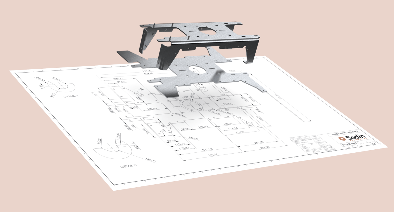
A rejected sheet metal part is more than a hassle. It leads to delays, extra costs, and wasted materials. One miscalculated bend or misplaced hole can mean scrapped parts and expensive rework.
Sound familiar? You’re not alone.
Many manufacturers face these design challenges, driving up costs and slowing production. Sheet metal design may look simple, but every detail matters. The good news? A few smart design choices can prevent these problems before they start.
At Sedin Engineering, we help manufacturers across the globe design stronger, more cost-effective, and production-ready sheet metal parts. Our Design for Manufacturing (DFM) approach ensures every part is optimized for smooth, and cost-effective production.
Tired of rejected components and costly rework? Read on to learn the key sheet metal design guidelines for strong, high-quality, and easy-to-manufacture parts.
Guidelines for Sheet Metal Design
1. Material Selection: Strength vs. Cost
Material choice plays a big role in sheet metal part design. As choosing the wrong one can lead to unnecessary weight, poor durability, or increased costs.
For example, if corrosion resistance isn’t a priority, stainless steel may be overkill. If weight matters, aluminium might be a better fit.
Some commonly used materials for sheet metal design are:
☐ Steel – Strong, cost-effective, good for general applications (but can be heavy and prone to rust if not coated)
☐ Aluminium – Lightweight, corrosion-resistant, ideal for automotive & aerospace (but weaker than steel and can be costlier)
☐ Galvanized Steel – Rust-resistant, perfect for outdoor use (but can be difficult to weld and modify).
Pro tip: Always match material selection with your application and manufacturing process. Not just price.
2. Sheet Metal Fabrication: Consider the Process
When designing sheet metal parts, it's important to consider the fabrication method. Every bend, hole, and feature should be compatible with the chosen process. This helps avoid production issues, reduces costs, and ensures a smooth production.
Key design considerations for some common sheet metal processes:
☐ Laser Cutting – Great for precise cuts and intricate designs but avoid sharp internal corners to prevent material stress. Keep hole diameters at least equal to material thickness to prevent distortion.
☐ CNC Machining – Ideal for tight tolerances and fine details. However, complex machining increases costs, so limit precision features to critical areas only.
☐ Punching – Efficient for repetitive hole patterns, but holes must be at least 1.5x material thickness apart to prevent distortion and tool damage.
☐ Bending – Design with a bend radius at least equal to the material thickness to prevent cracking. Ensure bends don’t interfere with nearby holes or cutouts.
☐ Stamping – Cost-effective for high-volume production but requires design simplification to match die constraints. Add necessary clearances to prevent stress concentrations.
Designing with the fabrication process in mind helps eliminate production challenges and reduces costly rework.
3. Material Thickness & Tolerances: Get It Right the First Time
Material thickness is another factor that plays a critical role in sheet metal fabrication. Choosing the right thickness ensures that parts are strong enough for their functionality without adding unnecessary weight or cost.
Keep these key points in mind when designing sheet metal parts:
☐ Match material thickness to the application – Thicker materials add strength but can be harder to bend or cut.
☐ Standard sheet metal gauges – Stick to standard gauges or parts. This helps control costs and simplifies fabrication.
☐ Tolerances – Tolerances ensure sheet metal parts fit and function correctly. If they’re too tight, costs increase; if too loose, parts may not assemble properly. That’s why specific tolerance guidelines must be followed.

☐ Geometric Dimensioning & Tolerancing – GD&T ensures sheet metal parts fit and work as intended without adding extra costs. Use it only where needed to keep manufacturing simple and efficient.

Manufacturers often fall into the trap of over-engineering their tolerances. This leads to increased rejection rates and production delays. Specify what’s critical—and loosen tolerances where it won’t affect the functionality.
4. Bends: Avoid Cracks & Warping
Bending sheet metal parts seems easy, but it’s where things often go wrong. For instance, if the bend radius is too small, you risk cracking or weakening the material.
☐ Bend Radius – Keep it at least equal to the material thickness to prevent failures.
☐ Hole Near Bends – Avoid bending too close to holes, as it can distort them. Place holes at least 2x the material thickness away from bends.
☐ K-Factor – When you bend sheet metal, the outer side stretches, and the inner side compresses. The K-factor helps calculate how much the material shifts, so the flat pattern is accurate before bending.
Ignoring the K-factor when designing sheet metal can lead to incorrect part dimensions and misalignment. Typically, the K-factor ranges from 0.3 to 0.5, depending on material and bending method.
☐ Bend Reliefs – Small cutouts at the bend line help prevent material tearing and ensure a clean, precise bend. Relief cuts should be at least 1.5x material thickness.
☐ Offset Bends – Used to create a step-like feature in sheet metal, reducing assembly issues. Maintain an offset height of at least 3x material thickness for manufacturability.
☐ Curls – Rounded edges that eliminate sharp corners, improving safety and strength. The minimum inside radius should be equal to the material thickness.
☐ Hems – Folded edges that increase part rigidity and remove sharp edges. The hem width should be at least 4x material thickness for effective forming.
If these guidelines aren’t followed, parts may crack or warp, which require costly rework or scrapping. You may lose thousands of dollars in rework due to an improper bending allowance. A small design adjustment can prevent those losses.
5. Hole Placement: Don’t Let Your Punch Tools Struggle
When holes are too close to the edge or each other, they can distort during punching or laser cutting.
☐ Keep holes at least 1.5x the material thickness from the edges to avoid tearing.
☐ Use standard hole sizes whenever possible—custom sizes mean higher tooling costs.
If holes are placed incorrectly, it can lead to tearing, inaccurate alignments, and even part failure during assembly. One overlooked hole placement can lead to rework, wasted materials, and lost production time.
6. Cutouts & Reinforcements: Strength Where It Matters
Flanges and notches add strength to sheet metal parts. But only if designed right. Too short, and they may not provide the needed support. Too long, and they might interfere with assembly.
☐ Flanges – Extended edges in sheet metal that improve strength and assembly. Keep the flange length at least 4x the material thickness for proper strength.
☐ Gussets – Reinforcement features that strengthen bends and prevent deformation under load. Ideal for high-stress applications. Ensure rounded edges and a height-to-width ratio of 1:3 or less to prevent stress concentration.
☐ Notches – Cutouts that assist in bending and fitting. To avoid weak points and cracking, the notch width should be at least 1.5x the material thickness.
☐ Corner Fillets – Rounded edges that reduce stress concentration and improve manufacturability. Use a minimum radius of 0.5x material thickness for better strength and ease of fabrication.
A poorly designed flange or gusset can lead to weak points, making the part more susceptible to failure under stress. Flanges, notches and corner fillets done right mean stronger parts and fewer production defects.
7. Welding vs. Fasteners: Smarter Assembly Decisions
Many manufacturers default to welding, but sometimes self-clinching fasteners are a better option. Why? They reduce welding time and eliminate warping issues.
☐ Use welding for: Heavy-duty structures requiring permanent joints.
☐ Use fasteners for: Thin sheet metal where heat distortion is a concern.
If welding isn’t necessary, avoiding it can cut costs, speed up assembly, and reduce material distortion. The right choice speeds up assembly and cuts unnecessary costs.
8. Lances, Dimples & Embosses: Strength Without Extra Parts
These are small deformations in sheet metal that add strength, ventilation, or mounting points without additional hardware.
☐ Lances – Small raised features that improve rigidity and allow airflow. Ensure proper spacing to avoid material tearing. The length should be at least 3x the material thickness for effective reinforcement.
☐ Dimples – Raised or recessed areas that improve stiffness or serve as mounting points. Maintain a depth of no more than 0.4x the material thickness to prevent distortion.
☐ Embosses – Raised sections that provide strength or serve as guides for fasteners. Keep a minimum clearance of 2x material thickness from bends or edges to avoid deformation.
Using these features strategically can reduce weight, improve durability, and simplify assembly.
Common Mistakes in Sheet Metal Design
Developing a new product is exciting, but sheet metal design isn’t as simple as it appears. That’s why mistakes are common. Here are some of the most frequent ones:
- Designing parts without considering manufacturability
- Placing holes or bends too close to edges
- Overcomplicating designs, leading to higher costs
- Ignoring material properties when selecting thickness and bends
ALSO READ: Everything you need to know about CAD modeling
Let’s Make Your Next Sheet Metal Design Efficient
Scrap, delays, extra costs — design mistakes add up fast. Wrong bend allowances, missing relief cuts, or tight tolerances can throw off production.
If you're facing these challenges, we're here to help. At Sedin Engineering, we design with fabrication in mind. Our engineers know sheet metal design guidelines inside out. We apply them with precision to ensure your designs meet fabrication standards.
If you’re looking for expert sheet metal design services, let’s talk. Our team designs with precision, so your parts fit right the first time—no costly rework. And to make manufacturing easier, we provide DXF files ready for laser cutting, CNC machining, or waterjet cutting.
- Need a design review? - Want a custom sheet metal design?
Contact us today.


