Detailed Engineering and Design
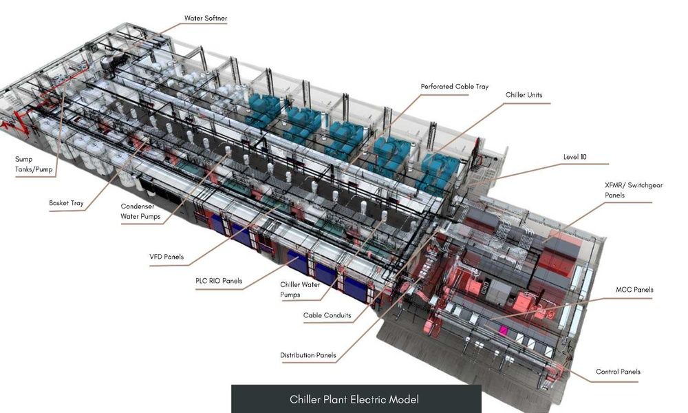
Chiller Plant Design and Optimisation through Electrical Design Modelling
Our client is an industrial manufacturing and engineering company specialising in modular mechanical/electrical architecture solutions. The company engaged our engineering design team to develop a model to enable the efficient operation of their chiller plant.
Scope
The company required support in developing an electrical routing and layout design for the chiller plant to ensure efficient and reliable operation.
We designed 3D models, including lighting design and calculations, based on the electrical equipment BOM, datasheets, SLDs, connection drawings, cable schedule, equipment plan layout, PID, network architecture, and supporting documents for other disciplines provided by the client.
We covered the main electrical disciplines as follows:
- Electrical Distribution and Lighting from E-House: Managing equal power distribution to the entire plant through the main electrical house. Implement a robust cable network using a combination of low-voltage and high-voltage panels to improve energy efficiency.
- Instrumentation and Control: Implement a structured approach to measure and adjust equipment operation across the plant through cables. Ensure signal integrity, operational reliability, and maintainability during cable routing.
- Telecommunication: Ensure logical segregation of power and communication circuits in the network and control network infrastructure. Ensure optimal communication between systems through an architecture that supports high-performance data and control communication.
- Security and Fire & Safety: Equip the plant with CCTV, Public Address systems, and comprehensive fire and safety systems to ensure optimal performance and protection.
- Lighting Design and Calculation: Provide safe, functional, and energy-efficient lighting across all areas of the chiller plant. Ensure uniform illumination in compliance with client specifications and international lighting standards.
Challenge
In addition to modelling for electrical disciplines, the following challenges were carefully considered while designing:
- Space constraints: Limited space for routing power, control, and communication cables in congested corridors and tight ceiling spaces. Accommodating large conduit bends and coordinating installations with mechanical and structural systems while maintaining the required bend radius.
- EMI risk: Potential signal interference caused by high-voltage cables and communication cables routed within confined trays.
- Environmental exposure: Considering the exposure of cables to extreme cold and heat zones, which causes physical stress such as overheating and corrosion.
- Rework during execution: Simultaneous integration with other services (fire protection, HVAC, piping) caused conflicts during cable routing, requiring rework. Changes from vendors required cable schedule and termination updates.
- Voltage drop concerns: Long cable runs between E-House and equipment require careful consideration for voltage drop, cable sizing, and grounding.


Solution
Our plant engineering services team focused on delivering a 2D/3D model based on the client’s inputs. The model also included rework, enabling efficient chiller plant optimisation and achieving up to 85-90% improvement in overall efficiency.
The design focused on clash-free cable routing, ensuring proper segregation between electrical systems, maintaining a reliable power supply and communication between control systems and adhering to electrical codes and standards.
1. Optimised Cable Routing
Cable trays and conduits were designed to prevent routing conflicts and ensure clear cable segregation.
- Resolved space constraints in cable-dense zones using layer-based trays, basket trays, and vertical risers to separate systems (power cable trays, fire & safety conduits, communication trays (CAT6, Fiber)).
- Minimum bend radius was maintained for the model, and smooth transitions were created between tray/conduit segments to avoid cable pulling.
2. Optimised Cable Segregation
High-voltage power cables and communication cables were physically separated to minimise EMI risk.
Communication cables were routed through the basket tray system, and power cables were routed at a minimum horizontal and vertical separation distance from communication cables.
3. Shielded Conduits and Fire Alarm Systems
Cables were routed through hazardous zones and high-interference areas using EMT, RGS, and PVC conduits.
- EMT – Cables were routed through lightweight electrical tubes for indoor electrical rooms.
- RGS – Cables that needed high mechanical protection from harsh outdoor environments required heavy-duty conduits.
- PVC – Cables exposed to wet zones were modelled for underground cable routing.
- Earthing conductors and bonding connections were modelled for trays and conduits to prevent electric shock.
4. Reduced Rework
Through mutual coordination, the client and the design team aligned their workflows to reduce errors. This alignment ensures smoother integration of the design model during cable scheduling, termination updates and cable clash detection.
The design was updated based on vendor inputs, site requirements, and equipment layout.
5. Voltage Drop Mitigation
Cable running from the main E-House to the equipment (VFDs and field motors) required careful routing and coordination while maintaining minimum bend radius.
- The E-House is equipped with low-voltage and medium-voltage panels for power distribution across the plant.
- 120/240V AC for low-voltage distribution routing towards smaller equipment at 80-85% efficiency.
- 480V AC for medium-voltage distribution routing from the main hub towards large motors and heaters at 85-90% efficiency.
Value and Benefits
Enabled accurate planning and execution of models using Revit. Integrated the electrical layout model with Navisworks for accurate clash detection and walkthroughs with construction teams.
Ensured regulatory compliance and safety by routing conduits and trays with applicable local electrical codes and following area-function-based lux level requirements.
Maintained clear separation between power and control conduits to prevent EMI interference by adhering to standards such as IEC 60364.
Improved coordination among electrical disciplines by modelling conduit terminations and tray dropouts to all major equipment (VFD panels, Chillers, cooling towers, motors and pumps).
Supported efficient cable routing and maintenance via smooth transitions between trays and conduits.
Ensured clear identification of conduit routes and colour-coded trays, ladder and basket trays for long-distance routing, and power distribution across the entire plant through E-House.
Related Case Studies


As-Built Revit Modelling for a Construction Company
As-Built Revit modelling enhances construction planning and efficiency through precise digital representations of existing structures.


Space-Efficient MEP Design for a Data Centre
Space-efficient MEP design maximises functionality in a confined data centre environment using innovative routing solutions.