Industrial Automation
End-of-Arm Tooling (EOAT) Design: Key Types & Considerations

By Alex A
Head of Engineering


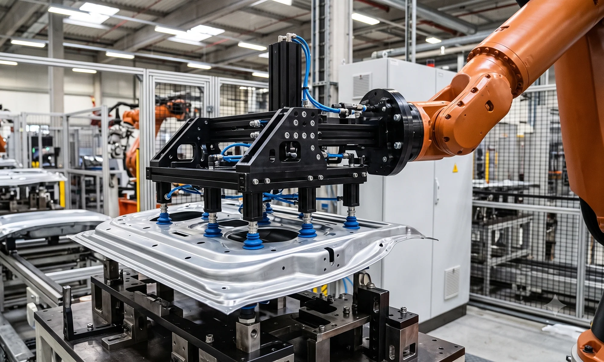
A robotic arm can have the right reach and payload, yet still struggle to handle a part effectively. The tooling mounted to its wrist has to do more than simply hold the workpiece. It must grip the part securely, maintain its position and move through the required path without interfering with fixtures or other equipment.
That is where end-of-arm tooling (EOAT) comes in. It connects the robot to the workpiece and is designed around the part and the process. Gripping method, tool weight, robot payload, accessibility, cycle time and sensor requirements all play a role in the final EOAT design.
This guide covers the main types of EOAT, key design considerations and the process of developing custom tooling for robotic applications.
What is End-of-Arm Tooling (EOAT)?
End-of-arm tooling (EOAT) is the tooling mounted to a robot wrist to interact with a workpiece. Depending on the application, it can grip, lift, position, move or perform a process on the part.
The tooling is designed around the part geometry, robot capabilities and process requirements. A complete EOAT assembly combines robot grippers, clamps and welding tools with supporting structures, sensors, actuators and other components needed for the application.
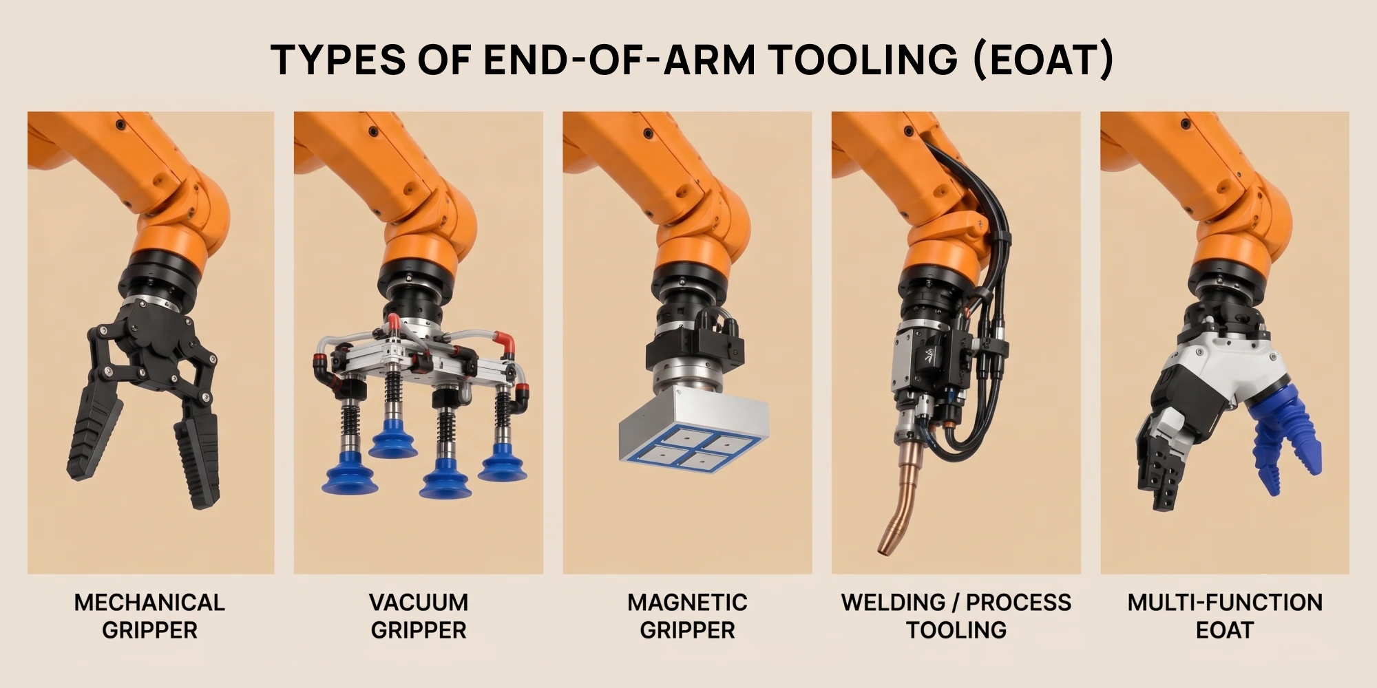
Types of EOAT
EOAT comes in different configurations depending on the part and the task the robot needs to perform. Each robot end effector is designed to suit the specific handling requirements, including part geometry, weight, surface condition and gripping points.
Mechanical grippers
Mechanical grippers use fingers, jaws, or clamps to hold a workpiece. They are commonly used for rigid components where the part can be gripped at defined points.
Common configurations include:
- Parallel two-jaw grippers for general part handling
- Three-jaw grippers for cylindrical or round components
- Collet and expanding mandrel grippers for gripping from an internal bore
- Multi-finger and adaptive grippers for irregular or varying part geometries
- Soft grippers for delicate or irregularly shaped parts
The gripping points and finger design should provide a secure hold without damaging or deforming the part.
Vacuum grippers
Vacuum grippers use suction cups to pick and transfer parts. They are commonly used for sheet metal, glass, plastic panels, cartons and similar components.
The size, number and placement of suction cups depend on the part's weight, shape, surface condition and required holding force. Vacuum sensors can also be used to confirm that the part has been picked correctly.
Magnetic grippers
Magnetic grippers use magnetic force to pick and hold ferromagnetic parts, like steel components. They can be useful for handling sheet metal and other parts where vacuum or mechanical gripping is not suitable.
The magnetic arrangement should provide enough holding force while still allowing the part to be released reliably.
Welding and process tooling
EOAT is not limited to part handling. Robot-mounted tooling can also be used for processes like welding, dispensing, cutting, drilling and inspection.
The tooling needs to accommodate the process equipment while staying within the robot's payload, reach and working-envelope limits.
Multi-function EOAT
Some applications require one tool to perform multiple tasks or handle different parts. A multi-function EOAT can combine grippers, clamps, sensors and process tooling in one assembly.
This can reduce tool changes, but it also adds weight and complexity. So, the design needs to balance functionality with robot capacity, accessibility and ease of maintenance.
Key EOAT design considerations
A good robot end-of-arm tool design needs to work with the part, robot and process. The tooling must provide a secure grip, stay within the robot's payload and motion limits, and operate reliably within the available workspace.
Designing EOAT for robot arm involves several key considerations:
Part geometry, weight and gripping method
The part's size, shape, weight, material and surface condition all matter when designing EOAT. These factors help determine where and how the part should be held and supported.
Different robot grippers suit different handling requirements. The tooling must hold the part securely without damaging critical surfaces or interfering with fixtures or other features.
For mechanical grippers, the fingers must provide enough force to prevent the part from slipping during robot movement and acceleration. Too little force can cause the part to move or fall, while excessive force may deform thin or delicate components.
Vacuum grippers require a different approach. Suction-cup size, number and placement depend on the part's weight, surface condition, vacuum level and potential air leakage.
Robot payload and tool rigidity
The combined mass of the end of arm tool and workpiece must stay within the robot's rated payload. Centre of gravity, tool offset, mass distribution and inertia also affect the loads on the robot wrist and should be considered during EOAT design.
Keeping the tooling compact and positioning heavier components closer to the robot wrist can help reduce these loads.
The EOAT also needs sufficient rigidity to limit deflection during robot movement and acceleration. Long tool extensions or flexible support structures can affect positioning accuracy and repeatability.
For cobots, EOAT weight and centre of gravity are especially important because their payload capacity is generally lower than that of larger industrial robots.
Reach, accessibility and collision clearance
The EOAT must allow the robot to reach all required pick, place, and process positions. Its size and shape can affect access to parts inside fixtures, machines and other restricted areas.
Gripper design for robotic arms must consider the tool size and approach direction, not just the gripping points. The gripper must be able to reach and handle the part without interference.
Clearance should be checked throughout the robot's full motion path. The EOAT must avoid fixtures, conveyors, guarding, machines and other tooling during operation.
Cycle time
EOAT design can directly affect the production cycle. Gripping and release time, actuator response, tool weight, robot acceleration and the number of parts handled in each cycle can all influence performance.
The tooling should support the required production rate without compromising grip, positioning accuracy or reliable operation.
Sensors and utility integration
Sensors can be added to the EOAT to detect part presence, confirm gripping, check position, or monitor the process. They should be positioned for reliable detection while remaining protected and easy to access.
Pneumatic cylinders, vacuum components, electrical connections, hoses and cables also need to fit within the tooling layout. Hoses and cables should be routed to allow robot movement without bending, snagging or interfering with nearby equipment.
These requirements make pneumatic and electrical integration an important part of robot end effector design, rather than something to consider after the tooling is complete.
Tool changing and maintainability
Some applications require a robot to handle different parts or perform multiple operations. A quick-change system allows different EOATs to be changed when needed.
The design should account for the tool-changer interface, repeatable positioning, and pneumatic or electrical connections. Grippers, sensors, fittings and actuators should also be easy to access for adjustment, replacement and maintenance.
Good access makes servicing easier and can help reduce production downtime.
EOAT design process
Robot end-of-arm tooling design starts with the application requirements and progresses from the initial tooling concept to a detailed, fabrication-ready design. Each stage is checked against the robot, part, process and automation cell requirements.
1. Define the application requirements
Start by understanding what the robot needs to do. Key inputs include the workpiece, handling process, cycle time, robot model, payload, reach and available workspace.
Part drawings, 3D models, fixture layouts, robot data and process requirements provide the information needed to develop the tooling.
2. Select the gripping method
The part and application determine how it should be held. Mechanical, vacuum, magnetic, or other gripping methods can be selected based on the part's geometry, surface condition, grip requirements and handling conditions.
The number and location of gripping points can then be established as the tooling concept develops.
3. Develop the EOAT concept
Once the gripping method is selected, the overall robot end effector design can be developed. This includes the robot mounting interface, grippers, support structure, sensors, actuators and pneumatic or electrical components.
The layout should provide the required grip and part support while allowing the robot to perform the required handling motion.
4. Check robot compatibility, reach and clearance
The proposed EOAT needs to be checked against the robot's payload, reach, wrist-load limits and mounting interface. The combined mass of the tooling and workpiece must remain within the robot's payload capacity, while centre of gravity and inertia should be checked against the robot manufacturer's specifications.
The tooling should also be checked at the required robot positions and throughout its movement path. This helps identify limited access, fixture interference, and potential collisions.
For more complex applications, robot simulation can be used to evaluate reach and potential collisions before the tooling is manufactured.
5. Develop the detailed design
Once the concept meets the main requirements, the EOAT can be developed into a detailed 3D model.
This includes structural members, brackets, grippers, sensors, actuators, mounting interfaces and utility routing. Components are arranged to provide the required strength and rigidity while keeping the tooling accessible for operation and maintenance.
6. Prepare manufacturing documentation
The detailed design is converted into the documentation required for fabrication and assembly. This may include manufacturing drawings, assembly drawings, BOMs and component specifications.
Clear documentation helps ensure the EOAT is manufactured and assembled according to the design.
EOAT applications
EOAT is used across a range of industrial automation applications. The tooling design depends on the part, robot, process, and handling requirements.
Automotive part handling
Automotive parts often require custom EOAT because of their size, shape and weight. Robot grippers, clamps and vacuum cups can be combined to support and position parts during transfer.
In one project, Sedin designed EOAT for automotive glass and tailgate handling, transferring the tailgate between the bonding station, inspection station and curing conveyor while handling the combined weight and ensuring precise placement.
BIW and welding
In BIW applications, EOAT is used to pick, position and hold body components. Tooling can include clamps, locators, pins and other features to position parts accurately. The EOAT also needs to work with the BIW fixtures used to locate and support the body components.
For robotic welding, the end-of-arm tool can carry a welding gun or combine welding and part-handling functions.
Machine tending
Machine-tending EOAT is used to load and unload equipment like CNC machines, presses and injection molding machines. Mechanical or vacuum grippers can handle raw parts, finished components and workpieces, with one tool sometimes designed for both loading and unloading.
Pick-and-place and assembly
For pick-and-place robotic system, EOAT is designed to move components quickly and repeatedly between locations. The tooling can handle one or multiple parts per cycle and can include features to locate and hold components during assembly.
Material handling
Material-handling EOAT moves parts between conveyors, pallets, fixtures and workstations. Depending on the application, the tooling can use simple grippers or larger vacuum and multi-point arrangements for panels and assemblies.
Inspection and process applications
EOAT can also carry inspection cameras, dispensing tools, cutting tools, drilling tools and other process equipment. In these applications, the tooling is designed around the equipment, process requirements and robot motion.
When do you need custom EOAT design?
Standard grippers and off-the-shelf tooling can work well for straightforward handling applications. Custom EOAT becomes more useful when the tooling needs to be designed around the part, robot, process or automation cell.
Custom EOAT design can be useful when:
- The part has complex or unusual geometry that standard grippers cannot handle effectively.
- Multiple parts or operations need to be handled with the same tool.
- Different part variants need to be handled with the same EOAT, requiring adjustable gripping points, interchangeable fingers or other flexible tooling features.
- Available space is limited, requiring a compact or application-specific tooling arrangement.
- Sensors, clamps, vacuum systems or process equipment need to be integrated into one assembly.
- Existing EOAT needs to be modified or redesigned for a new part, robot or production requirement.
When these requirements apply, custom EOAT can provide a better fit between the robot, tooling, workpiece and automation process.
Looking for EOAT design support?
Sedin provides custom EOAT design services for robotic automation, from tooling concepts through detailed design and manufacturing-ready documentation.
We design EOAT around your part, robot, process, and production requirements, including gripping, payload, reach, clearance, sensors and utility integration.
Need an end of arm tool designed for your application? Contact us to discuss your project.
For broader automation equipment requirements, see our Automation Machine Design Services.
Related Blogs


The Top 7 Challenges in BIW Welding (and How to Solve Them)
Explore key BIW welding challenges and practical solutions to improve quality, precision and consistency in automotive manufacturing.


Automated Packaging Systems for Modern Manufacturing
Tired of slow, manual packing? Discover how automated packaging systems help you pack faster, reduce errors, and save on labor costs.


Assembly Line Automation in 2026: Top Industries Driving Demand
Learn what assembly line automation is, which industries use it most, which processes are automated first, and how to choose the right automation partner for your factory.